Dynamic factor. A lifting hook is usually equipped with a safety latch to prevent the disengagement of the.
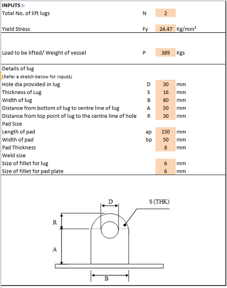
Lifting Lug Design Spreadsheet Calculator
Al 2009 this paper presents the different methods of stress calculation for lifting hooks based on different assumptions.
. Calculations were performed to the thermal expansion stress using finite element analysis such as linear. To attach the load locate the center of gravity position the crane hook directly above the center of gravity and then rig the load so that it will lift level and true. ASME BTH-1 specifies design calculations for different types of loading of a lifting device including tension compression flexure shear and combined loading of beams.
In this article we will explore the design of a basic lifting beam and see what design checks are needed to establish the suitability of the beam for a particular lifting operation. As a result different methods used to obtain the stress field on. Check lug shear stress.
Volume 1 24 cubic feet. Suction between the concrete element and the formwork can vary depending on the material and geometry of the casting bed. Forged Steel Wrought Iron.
Another important consideration is the centre of gravity of the load to be lifted together with any accessories and or attachments used - slings grabs shackles hooks magnets vacuum pads etc. 3C the sling lengths can be calculated using the following formulae. Bending stress in curved Beams This Crane hook is considered as the initially curved beam.
Element weight based on 2400-2500kgm3 is the initial start point for any lifting design. ASME BTH-1 Design of Below-The-Hook Lifting Devices governs the design of lifting lugs for industries. 2 2 2 sinq long sling length.
Ha q x A kN A. Other than for slings it appears that there are no inspection criteria for below-the-hook lifting devices in the OSHA. Steve Haberli shaberli Submitted On.
Max 1 ξ V L. FDESIGN FOR ADEQUACY OF PROVISION OF SINGLE LIFTING HOOKS. Ive never actually designed lifting hooks for a concrete slab before and would like to double check what Ive come up with and my reasoning.
First separate the object into rectangles and then calculate the weight of each section individually and then combine them as shown below. Formwork adhesion Ha is calculated through the following equation. First lifting hook minimum effort.
2 a H Ha. Check Bending and tension stress. F1min Gconc 2 Gsteel a1 b 1 p F1min 1101 2 033 183 366 1 20 F1min 454kN Second lifting hook maximum effort.
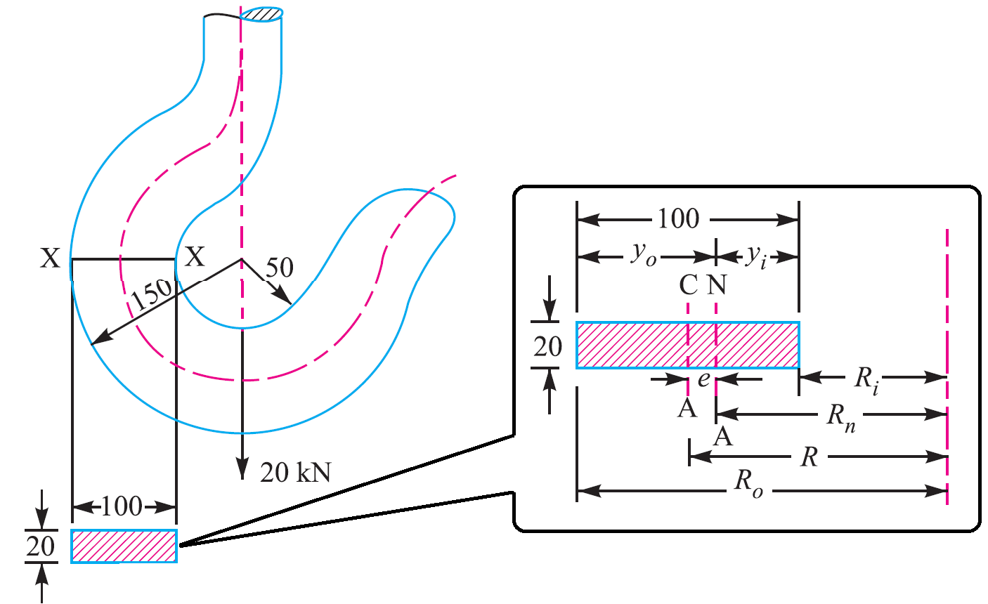
1 a H Ha. Heres how you would calculate the load weight of an irregular shaped object made out of concrete. The distance between neutral axis to the outside fibre Y o R o R n.
CBS12 Structural OP 2 Dec 09 0004. The quantity of effective lifting points may be less than the quantity of real lifting points if the system is not balanced. Depending on the style of lifting device only certain structural.
Section X-X height h 100 mm. Here is the situation. Help with lifting hooks for slab.
Lifting beams are universally applied gear used widely in various types of lifting operations onshore and offshore. For producing a safe reliable design This is the most widely used lifting lug design standard. As discussed in Reference 1 using a factor of 18 on AISC allowables results in a factor of safety of 5 for A36 steel.
Calculations to be made will include the capacity both of the overall beam and of the loading of the individual lifting points. Section X-X breadth b 20 mm. 1 5 min 1 xi.
Using the design calculation from the modeling the analysis of hook is done in FEA software This result lead us to the determination of stress in existing model. Dynamic Impact factor Fh fSQRTfxfx2fyfy2fx2 Iy2db223b312. 2 Design of C-hook.
Lifting hook design calculation Written By alfonzostraney88785 Saturday March 26 2022 Add Comment Edit. Anchorage length required L of each bar DL Dia Fbu 41336 mm Le 1000 mm Page 4 of 16. Area of this rectangular section X-X A Breadth b x Height h 20100 2000 mm².
Examples of detachable lifting equipment are shown in annex A. Q 2 kNm² for varnished timber mould. Min 1 ξ.
F2max Gconc 2 Gsteel a2 b γdyn γα 1 p F2max 1101 2 033 183 366 16 10086 1 20 F2max 1099kN. By predicting the stress concentration area the hook working life increase and reduce the failure stress. The lifting hooks can be classified into the single hook.
Q 1 kNm² for oiled steel mould. We have a slab design 24m x 19m and 200mm thick with a 600mm square opening and cover in the middle. However As such standards do not clearly address the local stress calculation steps Finite Element Analysis is performed using various.
Calculation Reference Machine Design Strength of Welds Design of Lifting Equipment Calculation Preview. Max 1 xi cdot V_ L. This is in line with ASME B3020 which requires a design factor of 3 on yield strength and ANSI N146 which requires a design factor of 3 on yield strength and 5 on ultimate.
Volume 1 Top 4 feet x 2 feet x 3 feet. INTRODUCTION Crane hooks are highly liable. A lifting hook is a device for grabbing and lifting loads by means of a device such as a hoist or crane.
DesignEvalution of Overhead Lifting Lugs Page 7 1. Minimum anchorage length provided Le assume 90 0 bend 1000 mm. 115 with ξ 03 for fixed crane or on rails and ξ 06 for crane bridge.
Expressed in terms of variables noted in Fig. Diameter used Dia 953 mm. By varying the lengths of chokers a fixed-tilt lifting beam can be made as depicted in Fig.
Area of contact between the mould and the concrete unit when starting to lift. Lifting lug calcsxls Lifting lug calcsxls. They applied curved beam theory Finite Element Method and photo elasticity experiments to obtain the stress field on the hook.
115 min1ξmax1ξV L. Tension on Sling T 1 2 V1 2 H1 2 12 Tension on Sling T 1 2 W legs sin a 1 2. Dynamic Amplification Factors Fh for LIGHT Packages.
Q 3 kNm² for rough timber mould. However there are a number of additional factors that need to be taken in to account.

Pdf Design And Strength Analysis Of A Crane Hook With A 500 Kg Lifting Capacity
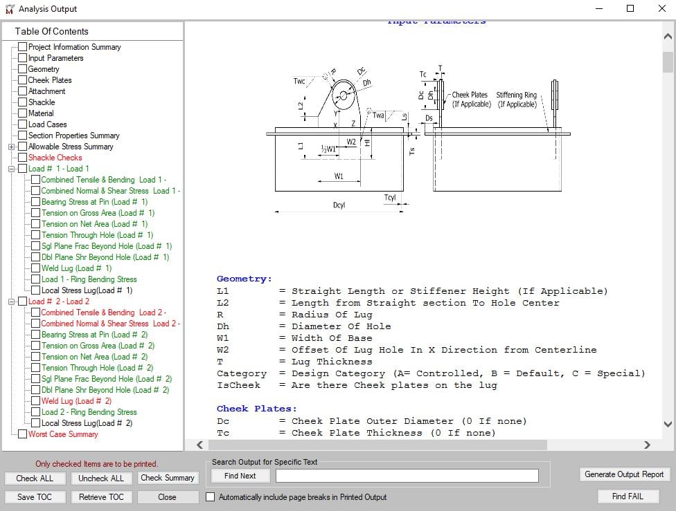
Lifting Lug Design Mecalug Software Meca Enterprises Inc

Lifting Lug Design With Example What Is Piping

Design Analysis And Weight Optimization Of Crane Hook A Review Semantic Scholar

Technical Drawing Of Hook Number 12 Download Scientific Diagram
Crane Hook Design Problem Sample Extrudesign
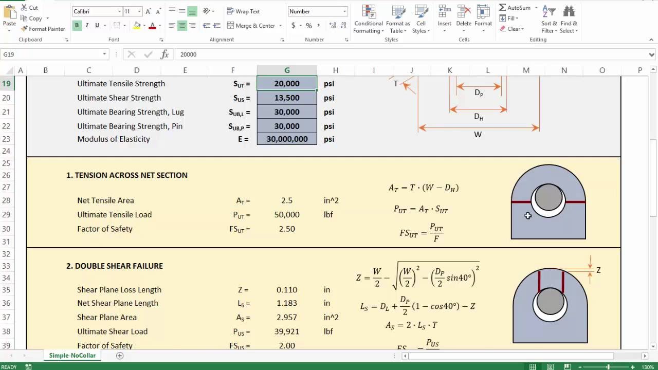
4 Lifting Lug Analysis Simplified Youtube

Lifting Lug Design Pv Elite Lifting Lugs Pressure Vessel Lifting Lug Design Code
0 comments
Post a Comment